Form: Frame Hinge Assignments
Nonlinear behavior in a frame object can be modeled by assigning nonlinear hinges along the length of the frame. Use the Assign menu > Frame > Hinges command to assign auto or user-defined hinge properties to selected frames. Several Frame Hinge Distribution Types are available:
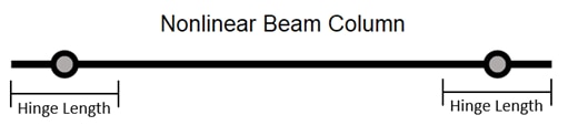
This option is intended to be used for most typical beam and column members which are governed by flexural behavior and expected to yield at one or both ends of the member while maintaining elastic or nearly elastic behavior at the mid-span. This option adds a moment or PMM hinge of a specified length at each end of the frame object.
Expected Hinge Length: Specify the expected hinge length, which is typically on the order of the depth of the frame section. This value may be specified by your local building code provisions. The hinge will be located half of the specified expected hinge length from the end offset at the I-end and J-end of the frame object, as illustrated below.
The Relative Length checkbox can be used to define the expected hinge length as a ratio of the total length of the selected frame object.
Hinge Property: This list includes available user-defined M2, M3 or PMM hinges and the Auto hinge option. If the selected hinge property is a stress-strain type or a Fiber hinge, the length of the hinge will be set equal to the specified Expected Hinge Length.
Selected Hinge: This displays the currently selected hinge property. If an Auto hinge property is selected, use the Modify/Show Auto Properties button to access the Auto Hinge Assignment Data form and view or modify the auto hinge properties.
Save individual fiber response for Fiber Hinges: This checkbox can be used to set whether the response of individual fibers in a Fiber hinge are saved for each step. Un-checking this option can be used in models with a large number of fiber P-M2-M3 hinges where the user may not be interested in viewing detailed fiber results for all hinges to reduce the size of the analysis results data files.
Note: If the Save Individual Fiber Response for Fiber Hinges option is not checked, the individual fiber results (stress, strain, state, and status) will not be available after analysis has been completed. Hinge response (hinge state and status) will be available.
This option is intended to be used for frame objects that are expected to have complex yielding behavior over the entire length, e.g. nonlinear buckling. Several integration types based on common quadrature rules are available, which determine the integration points and weights used for the nonlinear hinges along the length of the frame type. This option is intended to be used for a fiber hinge property but can also be used for other hinge types. When used with a fiber hinge property, both the elastic and nonlinear behavior of the frame in the hinge degrees-of-freedom is entirely governed by the hinges.
Integration Type: The hinge location and length based on the integration points and weights for the associated quadrature rules.
5 point Gauss-Lobatto. Because this integration type places hinges at the two ends of the frame object, it is most suitable for beam and column members in buildings where yielding starts at the ends of the elements.
5 point Gauss-Legendre.
7 point Gauss-Lobatto.
7 point Gauss-Legendre.
Hinge Property: This list includes all user-defined hinges and the Auto hinge option. If the selected hinge property is a stress-strain type or a Fiber hinge, the length of the hinge will be set equal to the integration weight corresponding to the specified integration type, as illustrated below.
Selected Hinge: This displays the currently selected hinge property. If an Auto hinge property is selected, use the Modify/Show Auto Properties button to access the Auto Hinge Assignment Data form and view or modify the auto hinge properties.
Save individual fiber response for Fiber Hinges: This checkbox can be used to set whether the response of individual fibers in a Fiber hinge are saved for each step. Un-checking this option can be used in models with a large number of fiber P-M2-M3 hinges where the user may not be interested in viewing detailed fiber results for all hinges to reduce the size of the analysis results data files.
Note: If the Save Individual Fiber Response for Fiber Hinges option is not checked, the individual fiber results (stress, strain, state, and status) will not be available after analysis has been completed. Hinge response (hinge state and status) will be available.
Note: The computation cost of analyzing nonlinear behavior in a frame object is proportional to the number of hinges assigned to the object. To improve analysis efficiency, we suggest using Distributed Plasticity only in objects where the expected nonlinear behavior cannot be represented with the Nonlinear Beam Column option.
.png)
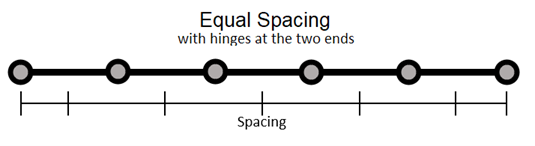
Similar to the Distributed Plasticity option, this can be used for frame objects that are expected to have complex yielding behavior over the entire length. This option adds evenly spaced hinges along the length of the frame object. This option can be used for all hinge types. When used with a fiber hinge property, both the elastic and nonlinear behavior of the frame in the hinge degrees-of-freedom is entirely governed by the hinges.
Spacing Type: Two options are available for specifying equal spacing hinge distributions:
Use the Max Spacing option to specify the maximum spacing between any hinge placed on the frame. If this option is used, the spacing between hinges may be smaller than the specified value. The number of hinges will be program-calculated.
Use the Number of Hinges option to specify the number of hinges to be distributed along the length of the frame. The spacing between each hinge will be program-calculated.
Place hinges at the two ends: When checked, a hinge will be located at the end offset at the I-end and J-end of the frame object, as illustrated below.
Hinge Property: This list includes all user-defined hinges and the Auto hinge option. If the selected hinge property is a stress-strain type or a Fiber hinge, the length of the hinge will be set equal to the spacing between hinges. If the Place hinges at the two ends option is selected, the hinges at both ends will be half length.
Selected Hinge: This displays the currently selected hinge property. If an Auto hinge property is selected, use the Modify/Show Auto Properties button to access the Auto Hinge Assignment Data form and view or modify the auto hinge properties.
Save individual fiber response for Fiber Hinges: This checkbox can be used to set whether the response of individual fibers in a Fiber hinge are saved for each step. Un-checking this option can be used in models with a large number of fiber P-M2-M3 hinges where the user may not be interested in viewing detailed fiber results for all hinges to reduce the size of the analysis results data files.
Note: If the Save Individual Fiber Response for Fiber Hinges option is not checked, the individual fiber results (stress, strain, state, and status) will not be available after analysis has been completed. Hinge response (hinge state and status) will be available.
Note: The computation cost of analyzing nonlinear behavior in a frame object is proportional to the number of hinges assigned to the object. To improve analysis efficiency, we suggest assigning only as many hinges as needed to capture the desired behavior.
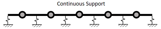
This option is intended to be used for piles or grade beams, which are supported by springs at specified intervals and are meshed at the intersection with these supports, to facilitate the placement of hinges between each support. This option adds one hinge at the center of every frame element associated with the selected frame object. If the frame object using this option is not meshed or divided into sub-elements, one hinge will be placed mid-span of the frame.
Hinge Property: This list includes all user-defined hinges and the Auto hinge option. If the selected hinge property is a stress-strain type or a Fiber hinge, the length of the hinge will be set equal to the length of the frame element that the hinge is assigned to.
Selected Hinge: This displays the currently selected hinge property. If an Auto hinge property is selected, use the Modify/Show Auto Properties button to access the Auto Hinge Assignment Data form and view or modify the auto hinge properties.
Save individual fiber response for Fiber Hinges: This checkbox can be used to set whether the response of individual fibers in a Fiber hinge are saved for each step. Un-checking this option can be used in models with a large number of fiber P-M2-M3 hinges where the user may not be interested in viewing detailed fiber results for all hinges to reduce the size of the analysis results data files.
Note: If the Save Individual Fiber Response for Fiber Hinges option is not checked, the individual fiber results (stress, strain, state, and status) will not be available after analysis has been completed. Hinge response (hinge state and status) will be available.
Note: The Continuous Spring Support hinge distribution type cannot be converted to User Defined. User Defined hinges cannot be added to a frame object with the Continuous Spring Support hinge distribution type assigned
This option allows full manual control over the number, position, and type of hinges assigned to the frame object. Each hinge assignment consists of a hinge property, a location of the hinge along the frame object, and an optional hinge length overwrite which applies to stress-strain or Fiber type hinges.
The Location Type option allows for the hinge position to be defined as either relative to the clear length of the frame object or as an absolute length from either end of the frame. The available options are as follows:
Relative To Clear Length. The hinge location is specified in the Relative Distance text box as a relative distance measured from the end offset at the I-end of the frame object toward the J-end of the object. The relative distance is a fraction from zero to one of the clear length of the object, i.e., the length of the object minus the length of any end offsets.
Distance From I End Offset. The hinge location is specified in the Absolute Distance text box as an absolute distance measured from the end offset at the I-end of the frame object toward the J-end of the object.
Distance From J End Offset. The hinge location is specified in the Absolute Distance text box as an absolute distance measured from the end offset at the J-end of the frame object toward the I-end of the object.
Note: More than one type of frame hinge can exist at the same location, for example, you might assign an M3 (moment) and a V2 (shear) hinge to the same end of a frame element. However, this may make it difficult to interpret some of the results.
The Length Overwrite Type parameter is an advanced parameter that can be accessed by enabling the Show Advanced Parameters option. This parameter is used to overwrite the hinge length parameter that is specified in the hinge property of a stress-strain or Fiber type hinge. This option is useful so that one hinge property can be used in multiple locations or frame objects without having to redefine the hinge property to change the hinge length setting. For example, one fiber hinge can be used to represent 20%, 30%, and 50% of the frame length by using this overwrite. The available options are as follows:
None. No hinge overwrite is applied so the assigned stress-strain or Fiber type hinge will be generated with the hinge length specified in the hinge property.
Relative. The hinge length overwrite is specified in the Relative Length text box as a fraction from zero to one of the clear length of the object, i.e., the length of the object minus the length of any end offsets.
Absolute. The hinge length overwrite is specified in the Absolute Length text box with length units.
The Save Individual Fiber Response? parameter is an advanced parameter that can be accessed by enabling the Show Advanced Parameters option. This parameter can be used to set whether the response of individual fibers in a Fiber hinge are saved for each step. Setting this option to No can be used in models with a large number of fiber P-M2-M3 hinges where the user may not be interested in viewing detailed fiber results for all hinges to reduce the size of the analysis results data files.
Note: If the Save Individual Fiber Response option is set to No, the individual fiber results (stress, strain, state, and status) will not be available after analysis has been completed. Hinge response (hinge state and status) will be available.
The Frame Hinge Assignment Data area shows a table of hinge assignments where each row is the parameters associated to one hinge assignment. The following buttons are used to add or modify the table:
Add Hinge. Use this button to add a hinge assignment with the chosen hinge property, location, and hinge length overwrite (advanced parameter).
Note: If the Auto option is selected from the Hinge Property drop-down list, the Auto Hinge Assignment Data form will display when the Add button is clicked. Use that form to specify the Auto Hinge Type based on tables in ASCE 41-13, ASCE 41-17, Caltrans Flexible, or JTG specifications.
Modify. Use this button to modify an existing hinge assignment in the table with the chosen hinge property, location, and hinge length overwrite (advanced parameter).
Note: If a row with an Auto hinge assignment is selected, hold the Ctrl key down when clicking the Modify button to access the Auto Hinge Assignment Data form and view or modify the auto hinge properties.
Delete. Use this button to delete an existing hinge assignment from the table.
The Convert to User Defined button can be used to convert a the hinge assignment data from a Nonlinear Beam Column, Distributed Plasticity, or Equal Spacing hinge distribution type to a User Defined hinge distribution type. This button allows the user to start a hinge assignment with a pre-defined hinge distribution and make additional changes if needed, such as adding a shear hinge in addition to the moment hinges provided by the Nonlinear Beam Column distribution type.
If the frame object(s) selected have existing hinge assignments, the radio buttons in the Options area provide the following options:
Add Specified Hinge Assigns to Existing Hinge Assigns. The specified hinge assignments in the form will be added to any existing hinge assignment data in the selected object(s). When used, all selected frame object(s) with a frame hinge distribution type of Nonlinear Beam Column, Distributed Plasticity, or Equal Spacing will be automatically converted to User Defined. This option will not affect frames objects which have the Continuous Spring Support distribution type.
Note: This option is only available for User Defined frame hinge distribution types. To use this option for other hinge distribution types, use the Convert to User Defined button to change the hinge definition to a User Defined distribution type.
Replace Existing Hinge Assigns with Specified Hinge Assigns. The specified hinge assignments in the form will replace any existing hinge assignment data in the selected object(s).
If a single frame object is selected, the Fill Form with Hinges on Selected Frame Object button in the Options area is enabled and can be used to populate the Assign Frame Hinges form with the hinge assignment currently applied to the selected object.
Override Axis Labels and Range
Override Structural Behavior Type